
Pumping Condensate from Vented Receivers
A basic introduction to pumping terminology, including vapour pressure and static head. Includes a description of the operation, application and comparable benefits of electrical centrifugal and mechanical condensate pumps, with sizing examples for pumps and pump discharge lines.
Pumping terminology
Pumping terminology
Vapour pressure - This term is used to define the pressure corresponding to the temperature at which a liquid changes into vapour. In other words, it is the pressure at which a liquid will boil.
- At 100°C, water will boil at atmospheric pressure.
- At 170°C, water will boil at a pressure of 7 bar g.
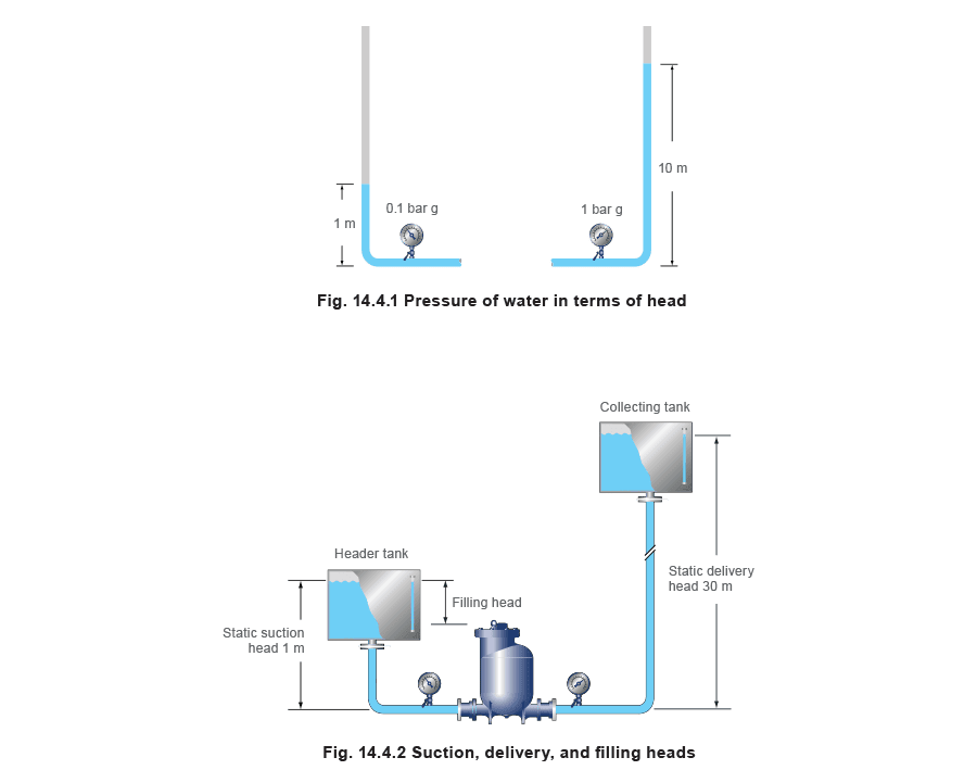
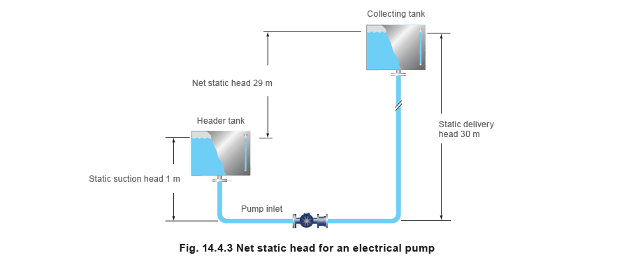
- At 90°C, water will boil at a pressure of 0.7 bar a. The vapour pressure is a very important consideration when pumping condensate. Condensate is usually formed at a temperature close to its boiling point, which may cause difficulties where a centrifugal pump is concerned. This is because centrifugal pumps have an area of lower pressure at the centre, or eye, of the impeller. This produces the suction effect, which draws the liquid into the pump. Although the drop in pressure is small, if the condensate is already very close to its vapour pressure, a proportion of the liquid will flash to steam in the form of small bubbles. These steam bubbles occupy a significantly greater volume than the equivalent mass of water, and have a high ratio of surface area to mass. As the bubbles travel through the impeller passageways towards its outer edge, they experience increasing pressure. At some point during this journey, the vapour pressure is exceeded, and the steam bubbles implode with considerable force. This is termed 'cavitation' and the implosions are both noisy and destructive. The noise is similar to gravel being shovelled and the implosions will, in time, damage the pump internals. For this reason, it is recommended that condensate be pumped by electrical pumps specifically built for the task, and that condensate temperatures in atmospheric systems do not exceed 98°C. Some pumps will have limits as low as 94°C or 96°C, depending on the design of the pump, the speed of rotation and the height of the receiver above the pump. Head (h) - Head is a term used to describe the potential energy of a fluid at a given point. There are several ways that head can be measured: pressure head, static head and friction head. Pressure head and static head are essentially the same thing, but tend to be measured in different units. Pressure head is measured in pressure units such as pascal or bar g; whilst static head is referred to in terms of height, usually in metres (or metres head). For water, a static head of 10 metres is approximately equivalent to a pressure head of 1 bar g (see Figure 14.4.1). Pressure head (hp) - Pressure head is the fluid pressure at the point in question. For example: A pump is required to discharge water against a static head of 30 metres, which approximately equals a pressure head of 3 bar g. The pump fills from a static head of 1 metre, which equals a pressure head of 0.1 bar g. (See Figure 14.4.2). Static head (hs) - Static head is the equivalent vertical height of fluid above a datum. The following example explains the measure of static head. Example: the pump inlet in Figure 14.4.2 is subjected to a static head (known as the suction or filling head) of 1 m, and discharges against a static head (known as the static delivery head) of 30 m. Note that in this case, the water being pumped is above the pump inlet (this situation is called a flooded suction).
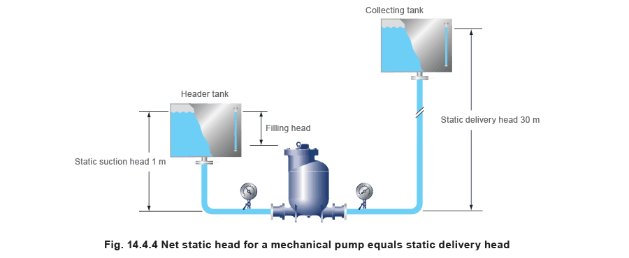
Net static head - This depends upon whether the pump is a centrifugal type pump or a positive displacement, mechanical type pump. With an electrical centrifugal pump (Figure 14.4.3), the pressure exerted by the suction head is always present in the pump. The net static head, against which the pump has to work, is the difference between the suction head and the delivery head.
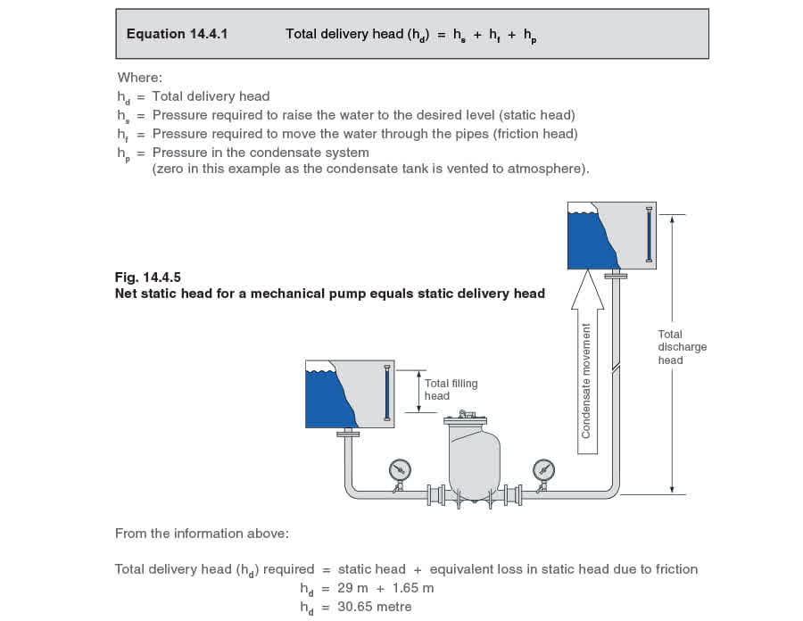
With a mechanical displacement pump (Figure 14.4.4), the suction head only provides the energy to fill the pump during the filling cycle. It is not present in the pump body during pumping and has no effect on the delivery head against which the pump has to operate. The net static head is simply the delivery head.
Friction head (hf) - The friction head (or head loss to friction) is more accurately defined as the energy required to move the fluid through the pipe. This is discussed in further detail in Module 10.2, 'Pipes and pipe sizing'. Pressure loss can be calculated using the procedures shown in Block 4, 'Flowmetering' and Block 10, 'Steam distribution', but is more usually found from tables that correlate liquid flowrate, pipe diameter and velocity. To be precise, the resistance to flow encountered by the various pipeline fittings must also be taken into account. Tables are available to calculate the equivalent length of straight pipe exerted by various pipe fittings. This extra 'equivalent length' for pipe fittings is then added to the actual pipe length to give a 'total equivalent length'. However, in practice, if the pipe is correctly sized, it is unusual for the pipe fittings to represent more than an additional 10% of the actual pipe length. A general rule, which can be applied, is: Total equivalent length (le ) = Actual length + 10% In most cases, the Steam Plant Engineer will be designing a system with a proprietary manufactured pump arrangement, which has appropriate factors built in. Bearing this in mind, the figure of 10% will be used in this Block as the equivalent length for calculating pressure loss due to friction. This pressure loss due to friction is greatly dependent on the velocity of the water in the pipe. In simple terms, the pressure loss due to friction increases by a factor proportional to the square of the velocity. Tables are available which give head loss per metre of pipe for various flowrates and pipe diameters.
Table 14.4.1 Flow of water in black steel pipes (kg/h)
| Pressure drop | Pipe size (mm) | |||||||||
| Pa/m | mbar/m | 15 | 20 | 25 | 32 | 40 | 50 | 65 | 80 | 100 |
| 100 | 1 | 184 | 425 | 788 | 1724 | 2 632 | 5 004 | 10 152 | 15 768 | 31 932 |
| 114 | 1.14 | 194 | 450 | 845 | 1 832 | 2 790 | 5 366 | 10 841 | 16 828 | 34 247 |
| 118 | 1.18 | 198 | 457 | 857 | 1890 | 2 830 | 5 443 | 11 022 | 17 055 | 34 746 |
Example 14.4.1 The 50 mm discharge pipework on a pumped condensate line rises vertically for 29 metres to a vented tank. The line is 150 m long and the pumping rate is 5000 kg/h of water. What is: (A) the pressure head loss due to friction (the friction head), and (B) the total delivery head? A - Calculate the pressure head loss due to friction (the friction head) Total equivalent length (le) = 150 + 10% = 165 metres From Table 14.4.1, it can be seen that a 50 mm pipe carrying 5004 kg/h of water will experience a pressure drop of 1.0 mbar /m. The flowrate in this example is marginally less, and, although a more accurate estimate could be obtained by interpolation, take the pressure drop as 1 mbar/m. Pressure head loss due to friction is therefore: 165 metres x 1 mbar/m = 165 mbar (0.165 bar) Taking 1 bar to be equivalent to 10 metres of water head the equivalent friction head loss in terms of metres is: 0.165 bar x 10 m/bar = 1.65 metres. B - The total delivery head Total delivery head (hd) - The total delivery head hd against which the pump needs to operate is the sum of three components as can be seen in Equation 14.4.1:
Electrical centrifugal condensate pumps
Electrical centrifugal condensate pumps
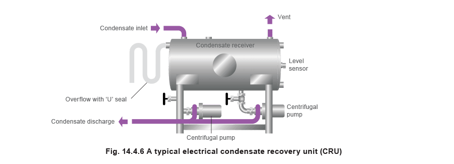
Pump operation Liquid entering the pump is directed into the centre, or eye, of the rotating impeller vanes. The liquid will then gain velocity as it travels towards the outside of the impeller. Pump application The electrical pump is well suited to applications where large volumes of liquid need to be transported. Electrical pumps are usually built into a unit, often referred to as a condensate recovery unit (CRU). A CRU will usually include: A receiver. A control system operated by probes or floats. One or two pumps. When calculating the frictional loss in the discharge line for a CRU, it is the pumping rate that must be considered as opposed to the rate of condensate returned to the receiver. On twin pump units, a cascade control system may also be employed which allows either pump to be selected as the lead pump and the other as a stand-by pump to provide back-up if the condensate returning to the unit is greater than one pump can handle. This control arrangement also provides back-up in the case of the one pump failing to operate; the condensate level in the tank will increase and bring the stand-by pump into operation. For cascade type units, the frictional loss in the discharge line is calculated on the maximum pumping rate of both pumps in the CRU. It is very important to follow the manufacturer's literature regarding the discharge pumping rate. Failure to do so could result in undersizing the pump discharge pipework.
Sizing an electrical condensate recovery unit To size an electric condensate recovery unit, it is necessary to know:
- The amount of condensate reaching the receiver at running load.
- The temperature of the condensate. This must not exceed the manufacturer's specified ratings to avoid cavitation, however, manufacturers usually have different impellers to suit different temperature ranges, for example, 90°C, 94°C and 98°C.
- The total discharge head the pump has to pump against - To be determined from the site conditions.
- The pump discharge rate in order to size the return pipework - It is necessary to read the manufacturer's data properly to determine this. Example 14.4.2 Sizing discharge pipework for an electric condensate recovery unit Where: Temperature of condensate = 94°C Condensate to be handled = 1 000 kg/h Static lift (hs) = 30 m Length of pipework = 150 m Condensate backpressure = friction losses only (hf) An initial selection of a condensate recovery unit can be made by using the manufacturer's sizing chart (an example of which is shown in Figure 14.4.7). From the chart, CRU1 should be the initial choice subject to frictional losses in the delivery pipework.
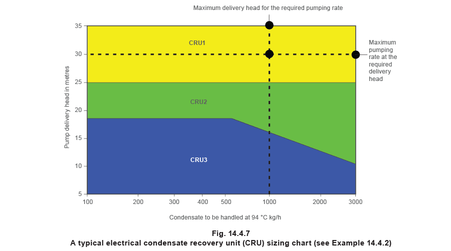
From the chart in Figure 14.4.7, it can be seen that CRU1 is actually rated to handle 3 000 kg/h of condensate against a maximum delivery head of 35 m.
The condensate return line is sized on the maximum pumping rate at the required delivery head, which is demonstrated in the example below: Maximum pumping rate = 3 000 kg/h It is this figure, 3 000 kg/h, that must be used to size the discharge pipework. It is now possible to calculate the optimum size for the return line. Actual length of pipework = 150 m Equivalent length of pipework = 150 m + 10% = 165 m Estimating the friction loss in the pipe (hf) To size a pumped discharge line it is usually a good idea to begin the friction loss calculation with an arbitrary pressure drop of between 100 and 200 Pa/m From the pressure drop Table 14.4.2 (extract shown below), it can be seen that, for a flowrate of 3000 kg/h, and for a pressure drop of between 100 and 200 Pa/m, a 40 mm discharge pipe will suffice.
Extract from Table 14.4.2
| Flowrate | kg/h | ||||||||||
| Pipe size Ø | 15 mm | 20 mm | 25 mm | 32 mm | 40 mm | 50 mm | 65 mm | 80 mm | 100 mm | ||
| Pa/m | mbar/m | <0.15 m/s | 0.15 m/s | 0.3 m/s | |||||||
| 100 | 1 | 184 | 425 | 788 | 1 724 | 2 632 | 5 004 | 10 152 | 15 768 | 31 932 | |
| 120 | 1.2 | 202 | 472 | 871 | 1 897 | 2 898 | 5 508 | 11 196 | 17 352 | 35 100 | |
| 140 | 1.4 | 220 | 511 | 943 | 2 059 | 3 143 | 5 976 | 12 132 | 18 792 | 38 160 | |
| 160 | 1.6 | 234 | 547 | 1 015 | 2 210 | 3 373 | 6 408 | 12 996 | 20 160 | 40 680 | |
| 180 | 1.8 | 252 | 583 | 1 080 | 2 354 | 3 589 | 6 804 | 13 824 | 21 420 | 43 200 | 1.5 |
| 200 | 2 | 266 | 619 | 1 141 | 2 488 | 3 780 | 7 200 | 14 580 | 22 644 | 45 720 | m/s |
It can be interpolated from Table 14.4.2 that a flowrate of 3 000 kg/h will correspond to a pressure drop of 128 Pa/m, for 40 mm pipework,
The head loss to friction can now be calculated for 40 mm pipework. Head loss to friction (hf) = 128 Pa/m x 165 m hf= 21000 Pa hf= Approximately 2.1 metres Establishing the total delivery head The total delivery head against which the pump has to discharge is therefore hs + hf = hd, where: hs= static lift of 30 m (given) hf = 2.1 metres hd= 30 m + 2.1 m = 32.1 metres The delivery head of 32.1 metres needs to be checked against the CRU manufacturer's sizing chart to confirm that the unit can pump against this amount of head. It can be seen from Figure 14.4.7 that this CRU can actually pump against a 35 metre head. Had the design head of 35 metres been exceeded, then the options are to re-calculate using a larger pipe, or to select a CRU with a greater lifting capacity. An alternative way to size the delivery pipework With an actual static head (hs) of 30 m, and a CRU design head of 35 m, a 5 m head is available for pipe friction losses (hf). It might be possible to install a smaller diameter pipe and have a larger friction loss. However, the designer must weigh this initial cost saving against the extra running power (and hence cost) required to pump against a larger head. Velocity also needs to be checked against a typical maximum of about 3 m/s allowable for pumped water at temperatures below 100°C. Table 14.4.2 will show that, if the next lower sized pipe (32 mm) were chosen, the unit friction loss (hf) to pass 3000 kg/h is interpolated to be 286 Pa/m, and the velocity is about 1 m/ s, which is below 3 m/s and therefore suitable for the application. hfis 286 Pa/m x 165 m = 47 190 Pa (or 4.72 m) Therefore, total delivery head (hd) = hs + hf hd= 30 + 4.72 m hd= 34.72 m The conclusion is that a 32 mm pipe could be used, as the CRU1 pump can handle up to 35 m total delivery head. However, from a practical viewpoint, it might not be reasonable to design a system to operate so close to its limits, and that, in this instance, 40 mm pipe would probably be the better solution.
Table 14.4.2 A section of a typical friction loss table for fully flooded pipelines (flowrates in kg/h)
| Flowrate | kg/h | ||||||||||
| Pipe size Ø | 15 mm | 20 mm | 25 mm | 32 mm | 40 mm | 50 mm | 65 mm | 80 mm | 100 mm | ||
| Pa/m | mbar/m | <0.15 m/s | 0.15 m/s | 0.3 m/s | |||||||
| 10 | 0.1 | 50 | 119 | 223 | 490 | 756 | 1 447 | 2 966 | 4 644 | 9 432 | |
| 12.5 | 0.125 | 58 | 133 | 252 | 554 | 853 | 1 634 | 3 348 | 5 220 | 10 656 | |
| 15 | 0.15 | 65 | 151 | 277 | 616 | 943 | 1 807 | 3 708 | 5 760 | 11 736 | |
| 17.5 | 0.175 | 68 | 162 | 302 | 670 | 1 026 | 1 966 | 4 032 | 6 264 | 12 744 | |
| 20 | 0.2 | 76 | 176 | 328 | 720 | 1 105 | 2 113 | 4 320 | 6 732 | 13 680 | |
| 22.5 | 0.225 | 79 | 187 | 349 | 770 | 1 177 | 2 254 | 4 608 | 7 164 | 14 580 | 0.5 |
| 25 | 0.25 | 83 | 198 | 371 | 814 | 1 249 | 2 387 | 4 860 | 7 596 | 15 408 | m/s |
| 27.5 | 0.275 | 90 | 209 | 389 | 857 | 1 314 | 2 513 | 5 112 | 7 992 | 16 200 | |
| 30 | 0.3 | 94 | 220 | 410 | 900 | 1 379 | 2 632 | 5 364 | 8 352 | 16 956 | |
| 32.5 | 0.325 | 97 | 230 | 428 | 940 | 1 440 | 2 747 | 5 616 | 8 712 | 17 712 | |
| 35 | 0.35 | 101 | 241 | 446 | 979 | 1 498 | 2 858 | 5 832 | 9 072 | 18 432 | |
| 37.5 | 0.375 | 104 | 248 | 464 | 1 015 | 1 555 | 2 966 | 6 048 | 9 396 | 19 116 | |
| 40 | 0.4 | 112 | 259 | 479 | 1 051 | 1 609 | 3 071 | 6 264 | 9 720 | 19 764 | |
| 42.5 | 0.425 | 115 | 266 | 497 | 1 087 | 1 663 | 3 175 | 6 480 | 10 044 | 20 412 | |
| 45 | 0.45 | 119 | 277 | 511 | 1 123 | 1 717 | 3 272 | 6 660 | 10 368 | 21 024 | |
| 47.5 | 0.475 | 122 | 284 | 526 | 1 156 | 1 768 | 3 370 | 6 876 | 10 656 | 21 636 | |
| 50 | 0.5 | 126 | 292 | 540 | 1 188 | 1 814 | 3 463 | 7 056 | 10 944 | 22 212 | |
| 52.5 | 0.525 | 130 | 299 | 558 | 1 220 | 1 865 | 3 553 | 7 236 | 11 232 | 22 788 | |
| 55 | 0.55 | 130 | 306 | 572 | 1 249 | 1 912 | 3 636 | 7 416 | 11 520 | 23 364 | |
| 57.5 | 0.575 | 133 | 317 | 583 | 1 282 | 1 958 | 3 744 | 7 596 | 11 808 | 23 904 | |
| 60 | 0.6 | 137 | 324 | 598 | 1 310 | 2 002 | 3 816 | 7 776 | 12 060 | 24 444 | |
| 62.5 | 0.625 | 140 | 331 | 612 | 1 339 | 2 048 | 3 888 | 7 920 | 12 312 | 24 984 | |
| 65 | 0.65 | 144 | 338 | 626 | 1 368 | 2 092 | 3 996 | 8 100 | 12 600 | 25 488 | |
| 67.5 | 0.675 | 148 | 346 | 637 | 1 397 | 2 131 | 4 068 | 8 280 | 12 852 | 25 992 | |
| 70 | 0.7 | 151 | 353 | 652 | 1 422 | 2 174 | 4 140 | 8 424 | 13 068 | 26 496 | |
| 72.5 | 0.725 | 151 | 356 | 662 | 1 451 | 2 218 | 4 212 | 8 568 | 13 320 | 27 000 | |
| 75 | 0.75 | 155 | 364 | 677 | 1 476 | 2 257 | 4 284 | 8 748 | 13 572 | 27 468 | |
| 77.5 | 0.775 | 158 | 371 | 688 | 1 505 | 2 297 | 4 356 | 8 892 | 13 788 | 27 972 | |
| 80 | 0.8 | 162 | 378 | 698 | 1 530 | 2 336 | 4 464 | 9 036 | 14 040 | 28 440 | 1 |
| 82.5 | 0.825 | 166 | 385 | 709 | 1 555 | 2 372 | 4 536 | 9 180 | 14 256 | 28 872 | m/s |
| 85 | 0.85 | 166 | 389 | 724 | 1 580 | 2 412 | 4 608 | 9 324 | 14 472 | 29 340 | |
| 87.5 | 0.875 | 169 | 396 | 734 | 1 606 | 2 448 | 4 680 | 9 468 | 14 724 | 29 772 | |
| 90 | 0.9 | 173 | 403 | 745 | 1 627 | 2 488 | 4 716 | 9 612 | 14 940 | 30 240 | |
| 92.5 | 0.925 | 176 | 407 | 756 | 1 652 | 2 524 | 4 788 | 9 756 | 15 156 | 30 672 | |
| 95 | 0.95 | 176 | 414 | 767 | 1 678 | 2 560 | 4 860 | 9 900 | 15 372 | 31 104 | |
| 97.5 | 0.975 | 180 | 421 | 778 | 1 699 | 2 596 | 4 932 | 10 044 | 15 552 | 31 500 | |
| 100 | 1 | 184 | 425 | 788 | 1 724 | 2 632 | 5 004 | 10 152 | 15 768 | 31 932 | |
| 120 | 1.2 | 202 | 472 | 871 | 1 897 | 2 898 | 5 508 | 11 196 | 17 352 | 35 100 | |
| 140 | 1.4 | 220 | 511 | 943 | 2 059 | 3 143 | 5 976 | 12 132 | 18 792 | 38 160 | |
| 160 | 1.6 | 234 | 547 | 1 015 | 2 210 | 3 373 | 6 408 | 12 996 | 20 160 | 40 680 | |
| 180 | 1.8 | 252 | 583 | 1 080 | 2 354 | 3 589 | 6 804 | 13 824 | 21 420 | 43 200 | 1.5 |
| 200 | 2 | 266 | 619 | 1 141 | 2 488 | 3 780 | 7 200 | 14 580 | 22 644 | 45 720 | m/s |
| 220 | 2.2 | 281 | 652 | 1 202 | 2 617 | 3 996 | 7 560 | 15 336 | 23 760 | 47 880 | |
| 240 | 2.4 | 288 | 680 | 1 256 | 2 740 | 4 176 | 7 920 | 16 056 | 24 876 | 50 400 | |
| 260 | 2.6 | 306 | 713 | 1 310 | 2 855 | 4 356 | 8 244 | 16 740 | 25 920 | 52 200 | |
| 280 | 2.8 | 317 | 742 | 1 364 | 2 970 | 4 536 | 8 568 | 17 388 | 26 928 | 54 360 | |
| 300 | 3 | 331 | 767 | 1 415 | 3 078 | 4 680 | 8 892 | 18 000 | 27 900 | 56 160 | |
Mechanical (positive displacement) condensate pumps
Mechanical (positive displacement) condensate pumps
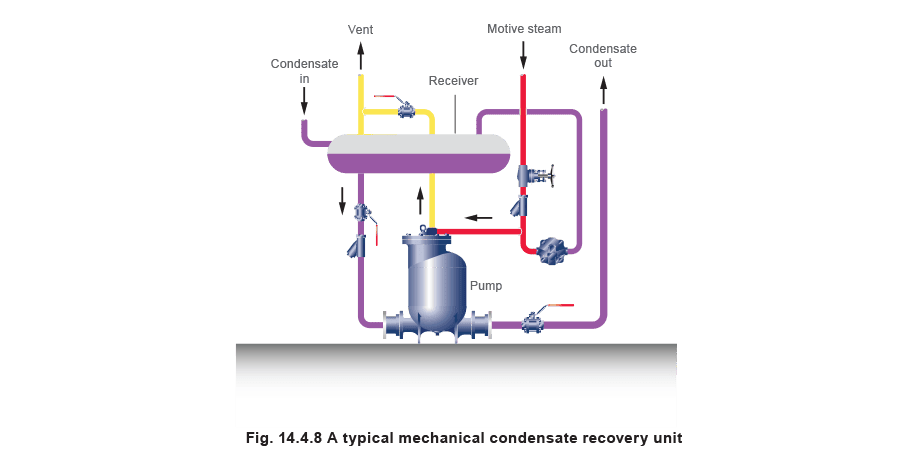
Pump operation A mechanical pump consists of a body shell, into which condensate flows by gravity. The body contains a float mechanism, which operates a set of changeover valves. Condensate is allowed to flow into the body, which raises the float. When the float reaches a certain level, it triggers a vent valve to close, and an inlet valve to open, to allow steam to enter and pressurise the body to push out the condensate. The condensate level and the float both fall to a preset point, at which the steam inlet valve shuts and the vent valve re-opens, allowing the pump body to refill with condensate. Check valves are fitted to the pump inlet and discharge ports to ensure correct directional flow through the pump. The cyclic action of the pump means that a receiver is required to store condensate while the pump is discharging (see Figure 14.4.8).
Pump application Generally, mechanical pumps handle smaller amounts of condensate than electrical pumps. They are however, particularly valuable in situations where:
- High condensate temperatures will cause cavitation in electrical pumps.
- Condensate is in vacuum.
- Plant room space is at a premium.
- Low maintenance is an issue.
- The environment is hazardous, humid or wet.
- Electrical supplies are not at hand.
- Condensate has to be removed from individual items of temperature controlled equipment, which may be subject to stall conditions (see Block 13 'Condensate Removal', for further details). As with electrically driven pumps, positive displacement mechanical pumps are sometimes, but not always, specified as packaged condensate recovery units. A mechanical condensate recovery unit will comprise a condensate receiver and the pump unit. No additional control system is required as the pump is fully automatic and only operates when needed. This means that the pump is self-regulating. With mechanical pumps, the pump cycles as the receiver fills and empties. The instantaneous flowrate while the pump is discharging can often be up to six times the filling rate and it is this instantaneous discharge flowrate, which must be used to calculate the size of the discharge pipe. Always refer to the pump manufacturer for data on sizing the pump and discharge line. A typical mechanical pump sizing chart is shown in Figure 14.4.10. Sizing a mechanical condensate pump To size a mechanical condensate pump, the following information is required: The maximum condensate flowrate reaching the receiver. The motive pressure of steam or air available to drive the pump. The selection of steam or air will depend on the application and site circumstances. The filling head available between the receiver and pump. The total delivery head of the condensate system. The method of sizing mechanical pumps varies from manufacturer to manufacturer, and is usually based on empirical data, which are translated into factors and nomographs. The following example gives a typical method for sizing a mechanical pump. (The pipe length is less than 100 m consequently friction loss is ignored): Example 14.4.3 How to size a mechanical condensate pump
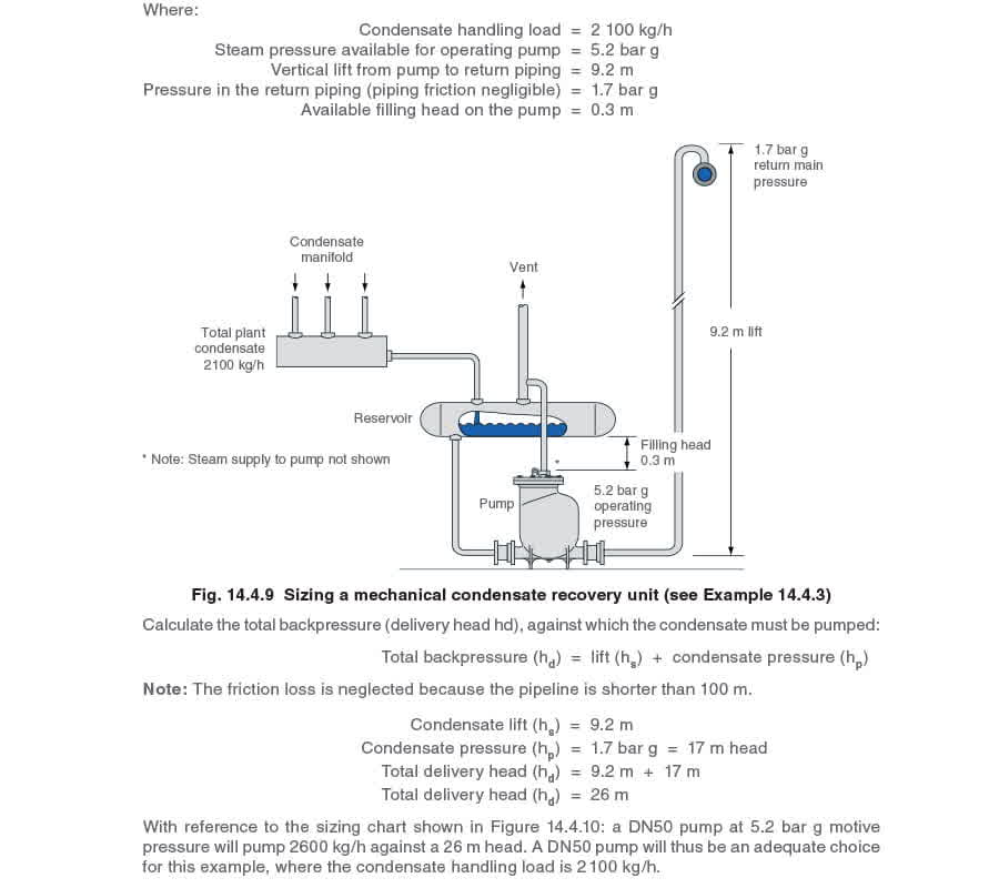
Sizing the discharge pipework for a mechanical condensate pump The discharge pipe from a mechanical pump can usually be taken to be the same size as the pump outlet when it is below 100 m long. The frictional resistance of the pipe is relatively small compared to the backpressure caused by the lift and condensate return pressure, and can usually be disregarded. For discharge pipes longer than 100 m, the general rule would be to select one pipe size larger than the pump outlet check valve, but for such longer lines, the size should be checked as shown in Example 14.4.4 Delivery lines longer than 100 metres On delivery lines over 100 m, and/ or where the condensate flow is near the pump capacity, it is advisable to check the pipe size to ensure that the total friction loss (including inertia loss) does not exceed the pump's capability. Inertia loss is explained in Example 14.4.4 Consider the same condensate pumping requirement as in Example 14.4.3 but with a delivery line 250 metres long. Example 14.4.4 Sizing a delivery line 250 m long (refer to Figure 14.4.10):
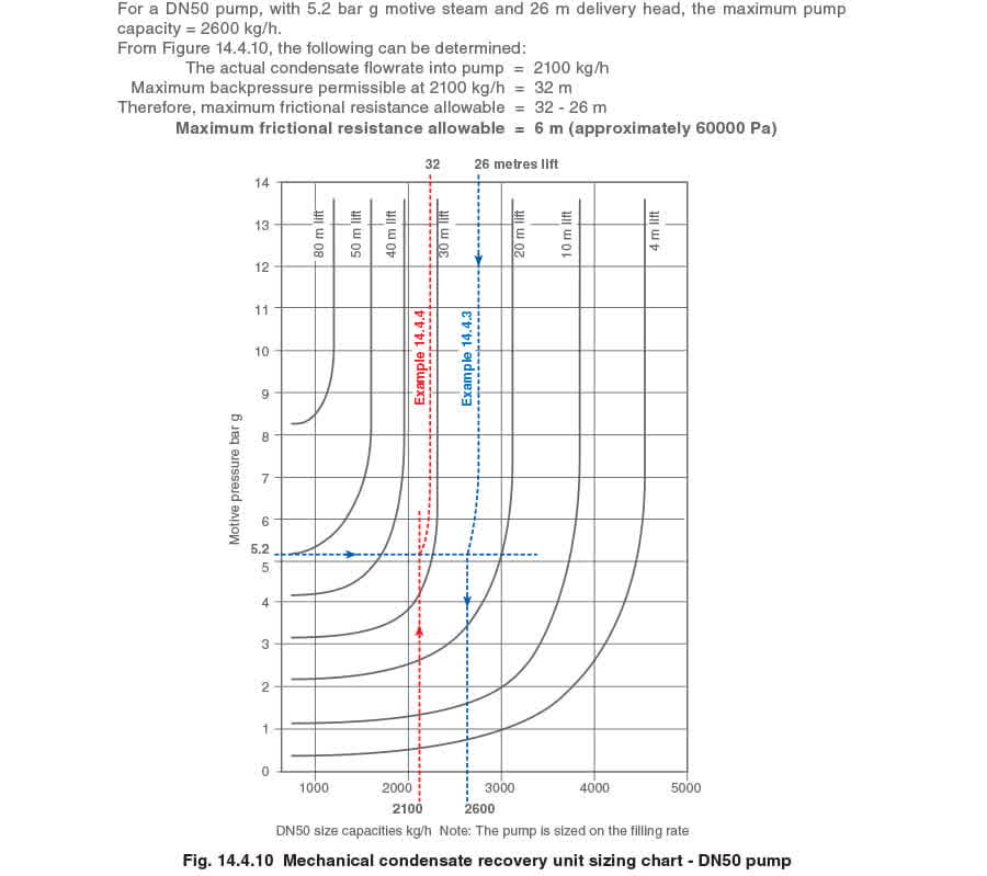
The effect of inertia loss on pump delivery lines longer than 100 metres. On lines over 100 m, a considerable volume of liquid will be held within the pump discharge pipe. The sudden acceleration of this mass of liquid at the start of the pump discharge can absorb some part of the pump energy and result in a large amount of waterhammer and noise. This needs to be considered within the calculation by reducing the allowable friction loss of 60 000 Pa in Example 14.4.4 by 50%, thus:
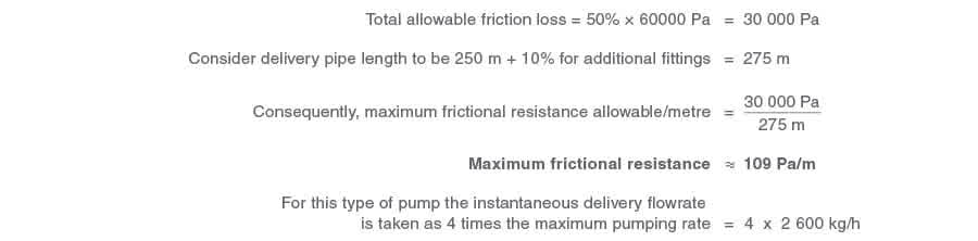
(This is based on the average time for the pump to discharge being approximately 25% of the total filling and discharge cycle time.)
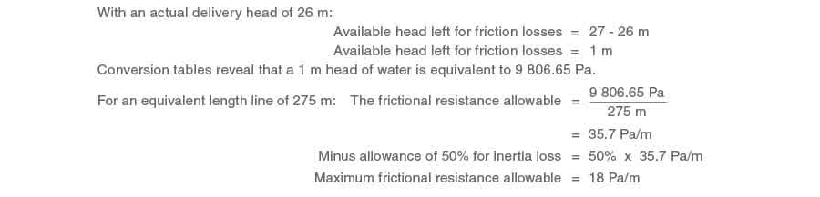
Therefore, the instantaneous delivery rate of condensate from the pump = 10 400 kg/h Total allowable friction loss With a frictional resistance of 109 Pa/m, Table 14.4.2 reveals that a 65 mm pipe (minimum) is required to give an acceptable flowrate of 10 400 kg/h. In fact, Table 14.4.2 indicates that a 65 mm pipe will pass 10 620 kg/h with a frictional resistance of 109 Pa /m. By rising up the '65 mm column' in the table, it can be seen that, by interpolation, the flowrate of 10 400 kg/h actually induces a frictional loss of 105 Pa/m in a 65 mm pipe. Fully loaded pumps and longer lines In Example 14.4.4, Figure 14.4.10 shows that the maximum pump filling rate with a motive pressure of 5.2 bar g and a delivery head of 26 metres is 2600 kg/h. Had the filling rate been close to this maximum, (perhaps 2 500 kg/h), then less delivery head would have been available for friction loss. For the same size DN50 pump, this would mean a larger delivery pipeline as shown in Example 14.4.5. Example 14.4.5 Consider the same DN50 pump as described in Example 14.4.4, but having a condensate filling rate of 2 500 kg / h. Now determine the size of the delivery pipeline.
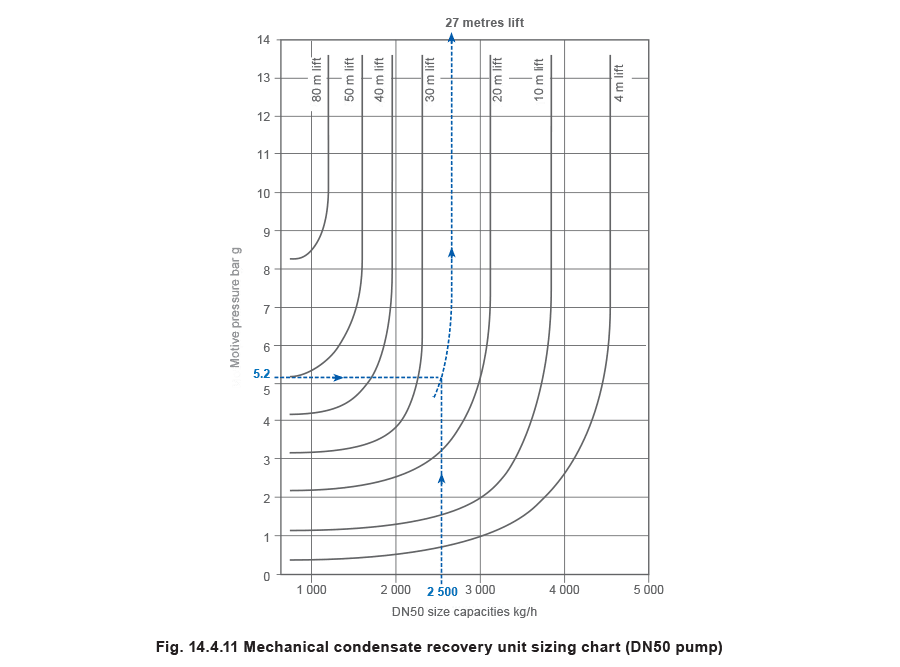
Sizing on a filling rate of 2500 kg/h, and a steam pressure of 5.2 bar, referring to Figure 14.4.11, for the DN50 pump, it can be seen that a condensate filling rate of 2 500 kg/h equates to a maximum backpressure of about 27 m, so in this instance:
The discharge pipework has to be sized on the instantaneous flowrate from the pump outlet, which is taken as 4 x maximum pumping rate. As before the pipe would have been sized on 4 x 2 600 kg/h = 10 400 kg/h with a friction loss of 18 Pa/m.
Table 14.4.2 shows that this would require a pipe diameter of 100 mm to allow the pump to operate within its capability. Although the system would certainly work with this arrangement, it is probably more economical to consider a larger pump in conjunction with a smaller pipeline. Considerations of a larger pump and smaller pipeline Consider the same pumping conditions as Example 14.4.4, but with a larger DN80 pump. As a larger unit can pump against a higher delivery head, a smaller delivery line can be used.
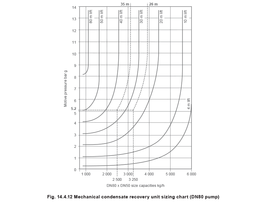
Figure 14.4.12 shows that a DN80 pump under the same conditions of 5.2 bar g motive steam and 2500 kg/h flowrate would allow a maximum delivery head of 35 m
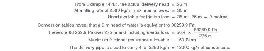
By interpolation, Table 14.4.2 shows that an 80 mm pipe will accommodate 20160 kg/h with a friction loss of 160 Pa/m, flowing at about 1 m/s.
In this instance, the larger DN80 pump will comfortably allow a pipe two sizes smaller than that for the smaller pump, and with a velocity of about 0.5 m/s, which is within recommendations. The 80 mm pipe is therefore suitable for the DN80 pump. In reality, a 65 mm pipe would be acceptable, since we have allowed for 50% inertia loss, however, this may look a little odd connected to a DN80 pump. Note: The DN80 pump would cost about 10% more than the DN50 pump, but the extra cost would be justified by the difference in installation costs on long delivery lines; which in this instance would mean the difference in cost between a 80 mm and 125 mm pipe; installation, fittings, and insulation. Condensate velocities Equation 14.4.2 can be used to check the condensate velocity.
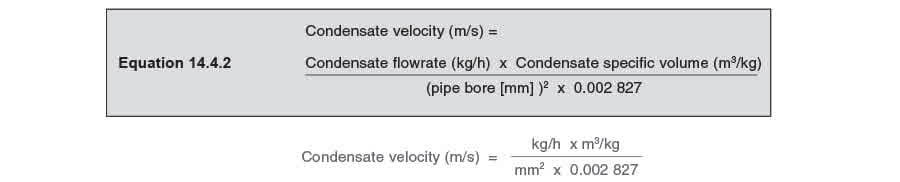
In Equation 14.4.2, the specific volume of water is taken to be 0.001 m3/kg. This value varies slightly with temperature but not enough to make any significant difference on condensate lines.
The condensate velocity can be checked for the 80 mm pipework in Example 14.4.4. 14.4.4.Example 14.4.4.

From Table 14.4.3 the maximum velocity for an 80 mm bore pipe is 1.84 m/s. Table 14.4.3 Maximum recommended velocities for pipe bores (based on a maximum friction loss of 450 Pa/m)
| Pipe bore, mm | 15 | 20 | 25 | 32 | 40 | 50 | 65 | 80 | 100 |
| Velocity, m/s | 0.62 | 0.8 | 1 | 1.23 | 1.27 | 1.5 | 1.8 | 1.84 | 2.4 |
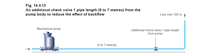
Best practice for long delivery lines
The momentum of the moving contents of a long delivery line may keep the water in motion for some time after a mechanical pump has completed its discharge stroke. When the water in the discharge pipe comes to rest, the backpressure in the line will attempt to reverse the initial flow of water, back towards the outlet check valve. The result is noise and pipe movement due to waterhammer, which can be both alarming and serious. Installing another check valve in the discharge pipe one pipe length from the pump will usually alleviate the problem.
If there is any choice, it is always best to lift immediately after the pump to a height allowing a gravity fall to the end of the line (Figure 14.4.14). If the fall is enough to overcome the frictional resistance of the pipe (Table 14.4.4), then the only backpressure onto the pump is that formed by the initial lift. A vacuum breaker can be installed at the top of the lift not only to assist the flow along the falling line but also to prevent any tendency for backflow at the end of the stroke.
Should the falling line have to fall anywhere along its length to overcome an obstruction, then an automatic air vent fitted at the highest point will reduce air locking and assist flow around the obstruction, see Figure 14.4.14.
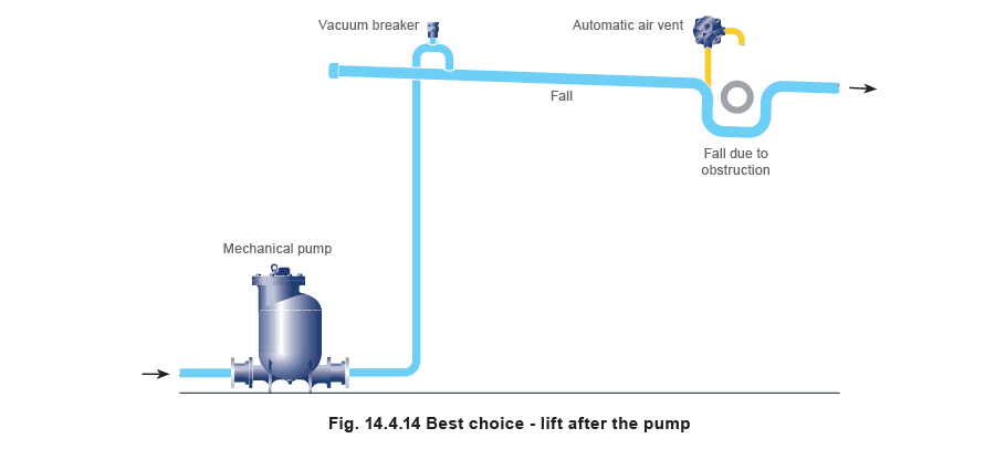
Table 14.4.4 Pipefall to overcome frictional losses
| Pipefall needed to overcome pipe friction | Pipe size (DN mm) | ||||||||||
| 15 | 20 | 25 | 32 | 40 | 50 | 65 | 80 | 100 | 125 | 150 | |
| Litres of water per hour | |||||||||||
| 25 mm in 15 m | 48 | 140 | 303 | 580 | 907 | 1 950 | 3 538 | 5 806 | 12 610 | 22 906 | 37 284 |
| 25 mm in 10 m | 59 | 177 | 381 | 694 | 1 134 | 2 449 | 4 445 | 7 257 | 15 680 | 28 576 | 46 492 |
| 25 mm in 8 m | 69 | 204 | 442 | 800 | 1 310 | 2 834 | 5 148 | 8 391 | 18 159 | 33 089 | 53 862 |
| 25 mm in 6 m | 79 | 231 | 503 | 907 | 1 487 | 3 220 | 5 851 | 9 525 | 20 638 | 37 602 | 61 223 |
| 25 mm in 5 m | 86 | 256 | 553 | 1 007 | 1 642 | 3 551 | 6 441 | 10 568 | 22 770 | 41 821 | 67 538 |
| 25 mm in 4 m | 93 | 279 | 598 | 1 093 | 1 778 | 3 878 | 7 030 | 11 521 | 24 811 | 45 994 | 73 571 |
| 25 mm in 3 m | 113 | 338 | 730 | 1 329 | 2 168 | 4 672 | 8 527 | 13 925 | 30 073 | 54 073 | 89 356 |
| 25 mm in 2 m | 140 | 419 | 907 | 1 655 | 2 694 | 5 851 | 10 614 | 17 327 | 37 421 | 68 039 | 111 128 |
| 25 mm in 1.75 m* | 152 | 454 | 984 | 1 793 | 2 923 | 6 327 | 11 498 | 18 756 | 40 573 | 73 708 | 120 426 |
| 25 mm in 1.5 m | 165 | 490 | 1 061 | 1 932 | 3 152 | 6 804 | 12 383 | 20 185 | 43 726 | 79 378 | 129 725 |
| 25 mm in 1 m | 206 | 612 | 1 324 | 2 404 | 3 923 | 8 482 | 15 422 | 25 174 | 54 431 | 99 019 | 161 476 |
*A fall of 25 mm in 1.75 m is equivalent to a fall of 1:70.
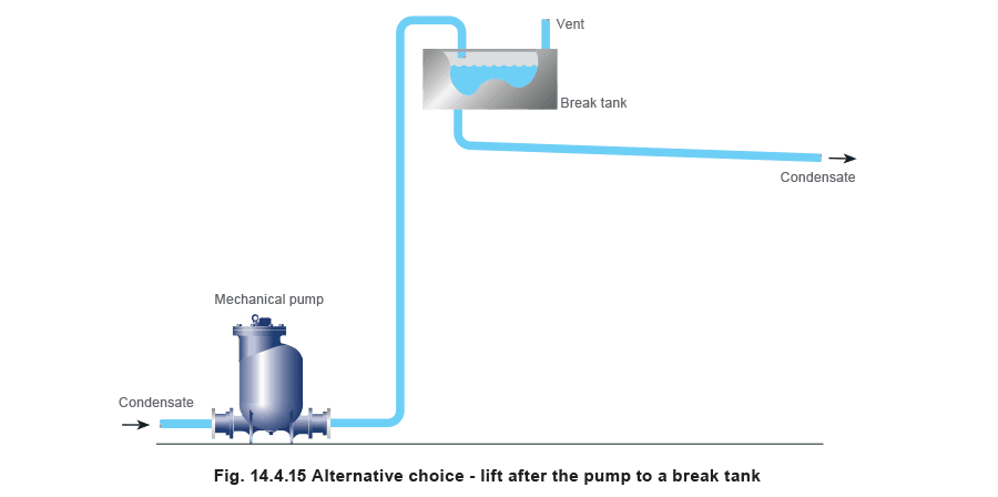
Alternatively, any question of backpressure caused by the horizontal run can be entirely eliminated by an arrangement as in Figure 14.4.15 in which the pump simply lifts into a vented break tank. The pipe from the tank should fall in accordance with Table 14.4.4.
Vented pumps, pumping traps and pump-trap installations
Discharge lines from pumps vented to atmosphere are sized on the discharge rate of the pump. Condensate passing through pumping traps and pump-trap combinations in closed loop applications will often be at higher pressures and temperatures and flash steam will be formed in the discharge line. Because of this, discharge lines from pumping traps and pump-trap combinations are sized on the trapping condition at full-load and not the pumping condition, as the line has to be sized to cater for flash steam. Sizing on flash steam will ensure the line is also able to cope with the pumping condition.